Firstly, not all distortion is bad and unwanted. Distortion can be deliberate e.g. the legendary 'soft' sound of tube amplifiers. Unlike transistor amplifiers, vacuum tube amplifiers generate distortion comprised of mainly even-numbered harmonics that are thus closely related to the fundamental frequency. This produces a sound that is quite pleasing to human ears.
On the other hand, when it comes to recording voice or music and reproducing it as close to the original as possible, then distortion is always undesirable. Classification and measurement of these unwanted distortions are discussed below.
Linear vs. non-linear distortion
A linear distortion is defined as a change in amplitude or phase with no new frequencies added.
A non-linear distortion occurs when new frequency components are generated. Non-linear distortions are what is usually meant by "distortion".
 original signal linear distorted signal non-linear distorted signal
Harmonic vs. no harmonic distortion
Non-linear distortions are further divided into harmonic or non-harmonic distortion. In harmonic distortion, all integer multiples of the fundamental frequency are considered. This is a classic distortion measurement called THD (Total Harmonic Distortion). In special applications, the total number of specific harmonics is considered. Non-harmonic distortions are those frequencies that are not multiples of the fundamental frequency, as is the case with IMD (intermodulation distortion).
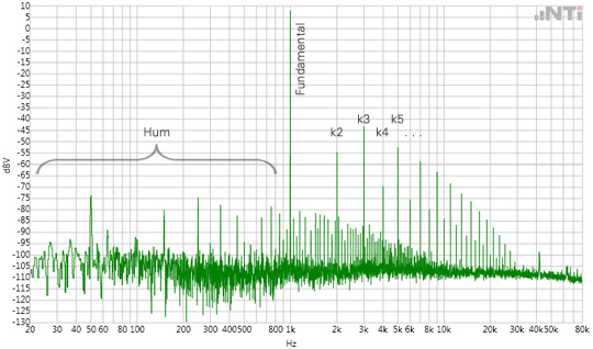
Harmonic Distortion Spectrum
THD vs. IMD
Devices that measure THD are widely available and easy to use. There is one major drawback for devices with low bandwidth range; for test signals with high frequencies, the harmonic distortions go out of range. For accurate readings, you need either a measurement system with a high bandwidth range, or you need to measure the IMD. For IMD measurements, two or more pure tones with independent frequency and amplitude are used as test signals. Non-linear distortions will then produce sums and differences of multiples of these input frequencies. The distortions are thus distributed throughout the entire analysis bandwidth.
Measurement and calculation methods
Distortions are almost always represented as ratios of signal to distortion. Results are typically expressed as a percentage (%) or in decibels (dB). The test signals may come from audio (electric) or acoustic (air) sources.
With THD there are two common methods of calculation. THD IEEE, used mainly in the USA, is calculated as the ratio of distortion to the fundamental frequency. THD according to the IEC method is common almost everywhere outside the USA and is calculated as the ratio of distortion to the sum of the original signal AND the distortion. In older measurement systems, signal noise is often added to the distortion, producing a THD + N value (N for noise). In every case, the analysis bandwidth range must be specified as this has a significant influence on the result.
With IMD measurements, there are three main methods used. The MOD method, in accordance with the IEC60268-3 standard, uses two tones with selectable frequencies and amplitudes. Intermodulation products of the 2nd-5th order harmonics are measured. The DFD (Difference Frequency Distortion) and CCIF methods work in a similar fashion, the difference being that the two frequencies are very close to each other and have the same amplitude. The DIM (Dynamic Intermodulation) method, commonly used in amplifier testing, employs a square wave signal and an additional modulation frequency.
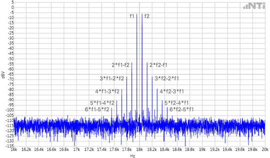
DFD (Difference Frequency Distortion) Spectrum
Which measurement instrument?
With simpler measuring systems, the distortion measurement is limited mostly to THD+N. For multi-channel and complex analysis, a modern system with a large bandwidth range and fast signal processors like a professional Audio Analyzer is needed.
Please note: Correct audio power and THD measurements only with the Burosch interface load box